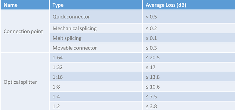
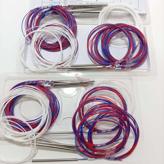
Fiber Optic Splitter has two main types, PLC fiber optic splitter and FBT fiber splitters. Whatever you choose for your application, You should take fiber splitter loss into consideration. There are some standard parameters for these splitters, if the fiber splitter loss is too much higher than this standards, It would be not good for your application.
FBT Fiber Optic Splitter Loss without Connectors
| Even Split Ratio | Insertion Loss (dB) |
|---|---|
| 1×2 | 3.6 – 4.0 |
| 1×3 | 5.0 – 5.5 |
| 1×4 | 6.2 – 7.0 |
FTTH PLC Fiber Optic Splitter Loss without Connectors


Let’s take a look Fiber Optic Splitter Loss separately. You can learn more details about Fiber Optic Splitter Loss with more factors considered.
1X2 FTTH FBT Fiber Optic Splitter Loss Chart
1X2 FBT Fiber Optic Splitter is almost the most used FBT Fiber Optic Splitter as it can be splitted with different ratios for projects. Here you can have the typical Loss Chart in the below:
| Parameter | Wide Band Coppler (WBC) | Dual Window Coupler (DWC) | Multimode Fiber Coupler (MMC) | ||||
| Grade | P | A | P | A | P | A | |
| Operating Wavelength (nm) | 1310, 1550 or C+L Band | 1310 and 1550 | 850 or 1310 or Specify | ||||
| Operating Bandwidth (nm) | ±40 | ±40 | ±40 | ||||
| Typical Excess Loss (dB) | <0.07 | <0.1 | <0.07 | <0.1 | <0.4 | <0.7 | |
| 50/50 | <3.4 | <3.6 | <3.4 | <3.6 | <3.7 | <4.0 | |
| 40/60 | <4.4/2.6 | <47/2.8 | <4.4/2.6 | <4.7/2.8 | <47/2.7 | <5.0/3.0 | |
| 30/70 | <5.7/1.9 | <6.0/2.0 | <57/1.9 | <6.0/2.0 | <6.0/2.1 | <6.3/2.4 | |
| 20/80 | <7.6/1.25 | <8.0/1.3 | <7.6/1.25 | <8.0/1.3 | <7.8/1.4 | <8.1/1.7 | |
| Insertion Loss(dB) | 10/90 | S10.65/0.65 | ^10.9/0.8 | 0.65/0.65 | <10.9/0.8 | 311.2/0.9 | ^11.6/1.2 |
| 5/95 | <13.8/0.4 | <14.1/0.5 | <13.8/0.4 | <14.1/0.5 | <14.5/0.7 | <15.0/1.0 | |
| 3/97 | <16.15/0.3 | <16.5/0.4 | <16.15/0.3 | <16.5/0.4 | <16.15/0.3 | <16.5/0.4 | |
| 2/98 | <18.05/0.25 | <18.45/0.35 | <18.05/0.25 | <18.45/0.35 | <18.6/0.6 | <19.4/0.9 | |
| 1/99 | <21.15/0.2 | <21.65/0.3 | <21.15/0.2 | <21.65/0.3 | <22/0.5 | <22.8/0.8 | |
| Polarization Dependent Loss (dB) | <0.1 | <0.15 | <0.15 | <0.2 | <0.1 | <0.15 | |
| Directivity (dB) | >50 | >35 | |||||
| Operating Temperature (°C) | -10 ~+70 | ||||||
| Storage Temperature (°C) | -40 〜+85 | ||||||
FTTH 1×3, 1×4, 1×5, 1×6 FBT splitter loss chart
| ConfigurationType | 1×3 | 1×4 | 1×5 | 1×6 | ||||
| Grade | P | A | P | A | P | A | P | A |
| Maximuminsertionloss(dB) | 5.8 | 6 | 6.8 | 7 | 7.8 | 8.5 | 8.7 | 9.5 |
| Uniformity(Max.)(dB) | 0.8 | 1 | 1.2 | 1.2 | ||||
| PolarizationDependantLoss(Max.)(dB) | 0.15 | 0.15 | 0.2 | 0.2 | ||||
| Directivity(dB) | >55dB | |||||||
| OperatingTemperature | minus 20°C ~ 85°C | |||||||
| StorageTemperature | -40°C~+85°C | |||||||
| FiberType | Corning Singlemode SMF-28 | |||||||
| FiberPigtailLength(m) | 1m or Custom on Request | |||||||
| PortConfiguration | 1×3 to 1X6 | |||||||
| OperatingWavelength(nm) | 1310+40,1550+40,1310/1550nm±40 | |||||||
Typical FTTH PLC Splitter Loss Chart
| Input x Output Port Number | 1×2 | 1×4 | 1×8 | 1×16 | 1×32 | 1×64 | ||
| Optical Fiber Diameter | um | 9/125 | ||||||
| Operating Wavelength | nm | 1260- 1650 | ||||||
| Insertion Loss (include PDL) | Typical | B | ≤ 3.6 | ≤7.0 | ≤ 10.3 | ≤ 13.6 | ≤ 16.6 | ≤20.1 |
| Max | B | 4 | 7.1 | 10.5 | 13.7 | 16.9 | 21 | |
| Uniformity’ Max | B | 0.5 | 0.7 | 1 | 1.5 | 2 | 2 | |
| PDL Max | B | 0.3 | 0.3 | 0.3 | 0.3 | 0.3 | 0.5 | |
| Return Loss | B | ≥50 | ≥50 | ≥50 | >50 | ≥50 | ≥50 | |
| Directivity’ | B | ≥ 55 | ≥ 55 | ≥ 55 | ≥ 55 | ≥ 55 | ≥ 55 | |
| Output Fiber Type | 4-fiberribbonx1 | 4-fiber ribbonx2 | 8-fiber ribbonx2 | 8-fiber ribbonx4 | 8-fiberribbonx8 | |||
| Case Size (For bare Fiber) | mm | 40(L)x4(W)x4(H) | 50(L)x7(W)x4(H) | 60()x12M) x4(H) | ||||
| Case Size* (For 0.9 LooseTube) | mm | 60(L)x7(W)x4(H | 60(L)x20(W)x4(H) | 80(L)x20 (W) x6(H) | 100(L)x40(W)x6(H) | |||
| Operation Temperature | ℃ | -40~ 85 | ||||||
| Characteristics Are Characteristics without connectors under room temperature at 1310nn/1550 nm | ||||||||
How to measure FTTH fiber optic splitter insertion loss with calculation?
The maximum allowable insertion loss for an optical splitter used in a PON system can be determined by using the calculations outlined in the below table.
| The maximum allowable insertion loss | |
| 1×N Optical Splitter | 0.8 + 3.4 log2N |
| 2×N Optical Splitter | 1.0 + 3.4 log2N |
| Note: ‘N’ denotes the number of output ports. | |
Conclusion
In certain areas, temperature can be a crucial factor that affects the insertion loss of optical components. FBT splitter can work stable under the temperature of -5 to 75℃. PLC splitter can work at a wider temperature range of -40 to 85 ℃, providing relatively good performance in the areas of extreme climate.
When it comes to wholesaling fiber optic splitters, You can contact bativ as your suppliers with good quality at low cost.