Fiber Optic Splitter
Fiber optic splitters define how feeder capacity is shared across subscribers and therefore influence optical budget, enclosure design, field labor, and expansion flexibility. Operators may place splitters centrally in a cabinet or hub, distribute them closer to homes, or stage splitting between a building entrance and floor terminals. Each architecture creates different requirements for package size, connectorization, fiber length, accessibility, and replacement.
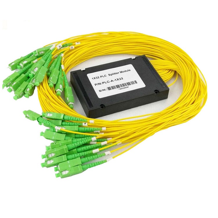
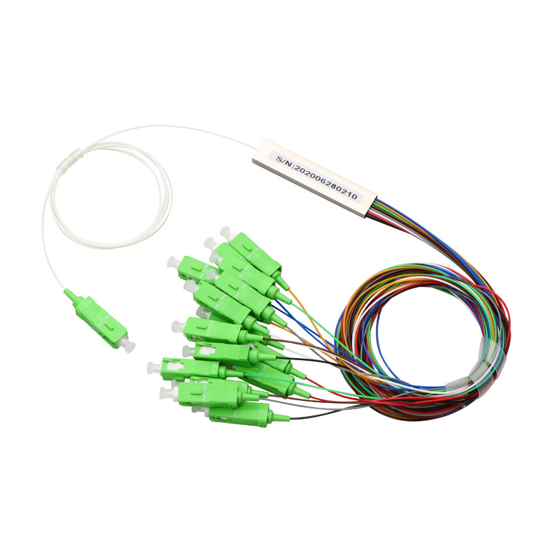
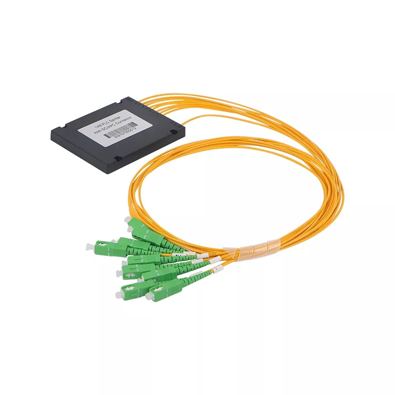
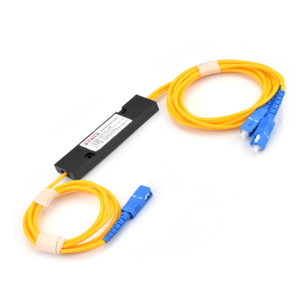
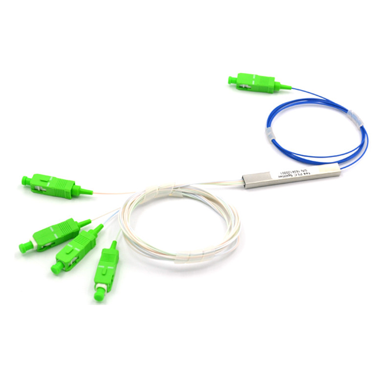
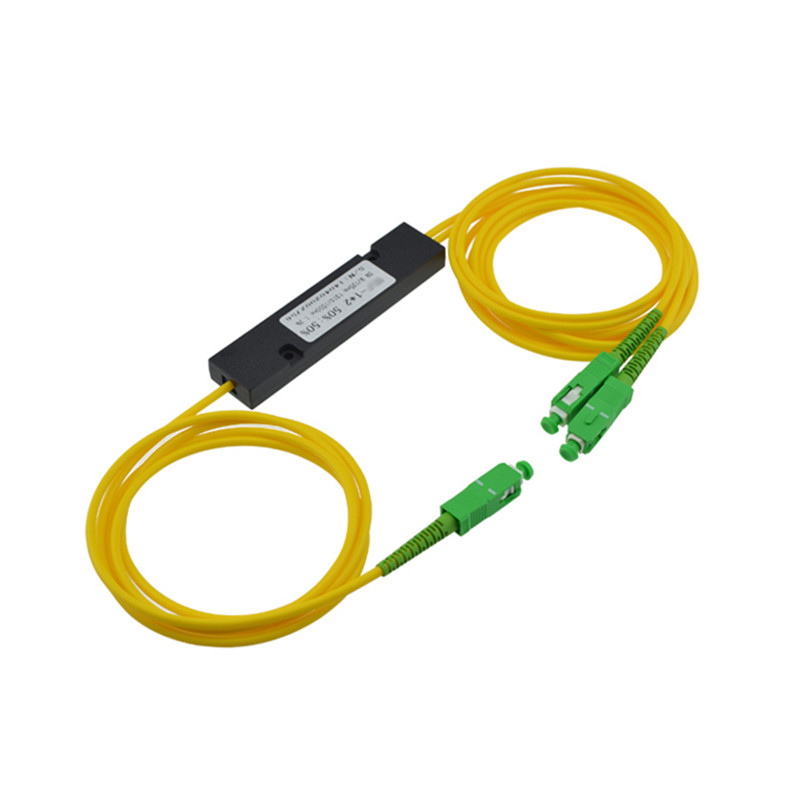
Selection should begin with split ratio and optical performance, including insertion loss, uniformity, return loss, operating wavelength, and reliability. The physical format is equally important. Bare fiber and steel-tube splitters suit compact splice trays, ABS modules protect fibers in boxes, cassette and tray formats simplify organized installation, and rack-mounted versions support central-office environments. Connector type, polish, fiber standard, pigtail length, labeling, and test documentation should align with the rest of the network.
Explore the products below according to architecture, installation location, package style, and termination method. Open the relevant product links to compare optical specifications, dimensional drawings, connector choices, test reports, packaging, custom labeling, and project-specific configurations.